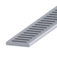
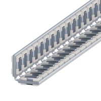
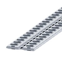
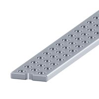
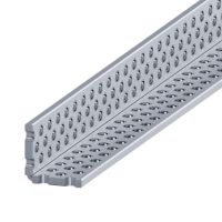
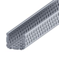
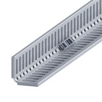
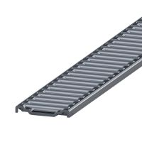
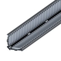
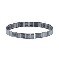
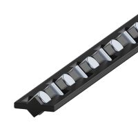
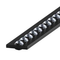
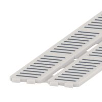
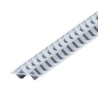
The linear bearing cage is an essential component of a linear rolling bearing built with the use of linear guides. The main task of the bearing cage is to hold the rolling elements inside the bearing on the guide's raceways in the correct operating position.
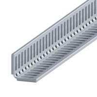
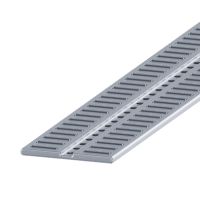
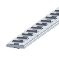
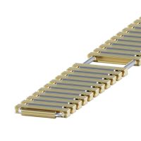
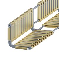
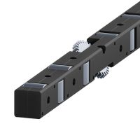
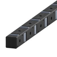
Flat metal single-row bearing cages with crossed bearing rollers
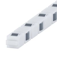
Made of stainless steel (RF) or brass (Ms)
Work with R, RD, GR, LWR and other cross roller slides.
With rollers holders.
Working temperature up to 150°C
Applicable to automatics, mechatronics, optomechanics
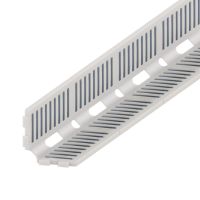
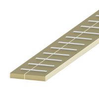
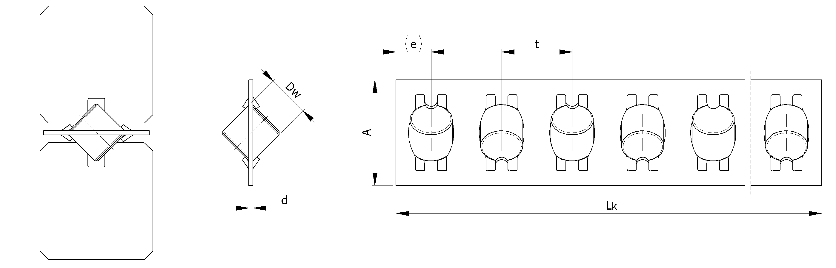
Technical drawing of AA bearing cages
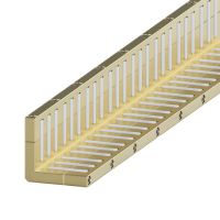
Dimension table of AA bearing cages
Roller
diameter
Ø
Type/symbol
Dimensions
Load capacity *
DW
t
A
d
e
C
[N]
CO
[N]
1.5
AA1
1.5
3
3.8
0.15
1.5
36.5
58.5
2
AA2
2
4
5.9
0.25
2
54
68
3
AA3
3
5
7.5
0.3
2.5
132
160
6
AA6
6
12
14
0.8
6
585
680
9
AA9
9
18
19.5
1
9
1700
1830
12
AA12
12
22
25
1.2
11
3000
3050
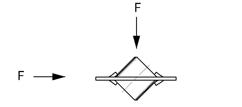
*) - Load capacity for 1 roller with the thrust force "F" in accordance to the drawing.
- C - dynamic load capacity, C0 - static load capacity
- The load capacity is calculated for guides with hardness of 60 +/- 2 HRc oand surface roughness of Ra<0.4.
- Load capacity of bearing cages is calculated on the basis of number of bearing needles mounted in the cage
- Length tolerance LK +0/-t
Weight table of AA bearing cages
Table for weight values of bearing cages
(for the length of 100 rollers) [g]
Type/symbol
Steel
Braas
AA1
3.0
3.1
AA2
6.6
6.8
AA3
22.5
33.5
AA6
165.6
199.6
AA9
6395
-
AA12
13900
-
MsBrass
FSteel
Precision
Sorting tolerance
up to 0.5 µm
Quality
Quality Management System
compliant with ISO 9001:2015
Experience
Over 20 years of expertise
in linear technology.
Customization
We manufacture components
tailored to individual requirements