
Rolled ball screw assemblies


Manufacturing Process
Rolled ball screw threads are precision-formed with special rollers and undergo enhancement processes including annealing, hardening, tempering, straightening, polishing, and precise measurement.
Accuracy Classes
Steinmeyer classifies rolled ball screws according to ISO 3408 part 3 – as transport ball screws in tolerance class T5 through T10.
Lead error

Table limit ep for the average lead error e0a [µm]
| Limit ep for the average lead error e0a [µm] | ||||
|---|---|---|---|---|
| lu [mm] | T5 | T7 | T9 | T10 |
|
200-315
|
23
|
52
|
130
|
210
|
|
315-400
|
31
|
69
|
173
|
280
|
|
400-500
|
38
|
87
|
217
|
350
|
|
500-630
|
48
|
109
|
273
|
441
|
|
630-800
|
61
|
139
|
347
|
560
|
|
800 - 1000
|
77
|
173
|
433
|
700
|
|
1000 - 1250
|
96
|
217
|
542
|
875
|
| 1250 - 1600 | 123 | 277 | 693 | 1120 |
| 1600 - 2000 | 153 | 347 | 867 | 1400 |
| 2000 - 2500 | 192 | 433 | 1083 | 1750 |
| 2500 - 3150 | 242 | 546 | 1365 | 2205 |
| 3150 - 4000 | 307 | 693 | 1733 | 2800 |
| 4000 - 5000 | 383 | 867 | 2167 | 3500 |
| 5000 - 6300 | 483 | 1092 | 2730 | 4410 |
Bearing Journals
The mounting should allow for rotation of the shaft and simultaneously pass the axial force on the ball screw into the adjacent construction with as little deformation as possible. Modern ball screw drives have very high load bearing capacity and stiffness, such that only high-quality bearings that are optimized for drive screw mounting can adequately meetrequirements. An attachment to the shaft that is adequate for the axial and prestressing force of this bearing is of crucial importance.


Drwg. no. 1 The most simple and costeffective option consists of a bearing journal that is sufficiently small compared to the nominal diameter of the shaft. Ideally, the shoulder surface underneath the minor diameter of the shaft can sufficiently absorb the force without deformation.


Drwg. no. 2: If the full shoulder is not sufficient, a shrunk-on ring with an exterior diameter larger than the shaft diameter is necessary.
Bearing selection
The support bearing of a ball screw should be able to absorb the axial force produced by the nut and the lateral forces from the belt drive. It can sometimes be difficult to find a suitable bearing for ball screws with large cycle criteria, and high load rating. At the same time, the bearing should have a sufficiently small inner ring bore hole and a supporting diameter no larger than the shaft nominal diameter.
This discussion thus only represents an initial point of reference for selection of bearings. It is by no means meant to be universally applicable or complete. The following criteria apply to the selection of a bearing:
Commonly used bearings
Steinmeyer recommends installing INA (angular) ball bearings. The following chart is an overview of commonly used bearings. Since it is not possible to display all combinations here, we ask that you consult with us for your special applications.
Table of INA mounting selection for fixed bearings
| INA mounting selection for fixed bearings | ||
|---|---|---|
| Ball screw drive Nominal- ø [mm] | Acc. to drwg. no. 1 above [conform to standard machining A described below] | Acc. to drwg. no. 2 above |
|
16
|
ZKLN1034
|
ZKLN1242
|
|
20
|
ZKLN1242 | ZKLN1545 |
|
25
|
ZKLN1747 | ZKLN2052 |
|
32 [P = 5]
|
ZKLN2557 | - |
|
32 [P >= 10]
|
ZKLN2052 | ZKLN2557-2AP |
|
40 [P = 5]
|
ZKLN3062 | - |
| 40 [P >= 10] | ZKLN2557-2AP | ZKLN3062-2AP |
| 50 | ZKLN3572-2AP | ZKLN4075-2AP |
| 63 | ZKLN4075-2AP | ZKLN5090-2AP |
| 80 | ZARN5090-TV | ZARN50110-TV |
Table of bearing selection for loose bearings
| Bearing selection for loose bearings | ||
|---|---|---|
| Ball screw drive Nominal ø [mm] | Loose bearing (coform to standard machining B described below) | Locking ring acc. to DIN 471 |
|
16
|
6200
|
10x1
|
|
20
|
6201
|
12x1
|
|
25
|
6203
|
17x1
|
|
32 [P = 5]
|
6204
|
20x1.2
|
|
32 [P >= 10]
|
6204
|
20x1.2
|
|
40 [P = 5]
|
6206
|
30x1.5
|
| 40 [P >= 10] |
6206
|
30x1.5
|
| 50 | 6207 | 35x1.5 |
| 63 | 6210 | 50x1.5 |
| 80 | 6212 | 60x2 |
Bearing Journals- standard machining
Ball screw ends are usually machined as specified in the customer's drawing. To choose this option, enter the letter 'Z' into the order code and attach the corresponding drawing. It is also possible to choose from the following fixed and loose bearing configurations.
Technical drawing of fixed bearing journals: A

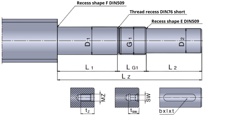
Dimension table for fixed bearing journals
| Fixed bearing journals: A | Machining options: K- hexagonal socket, G- internal thread, N- keyway groove | |||||||||||||||
|---|---|---|---|---|---|---|---|---|---|---|---|---|---|---|---|
| Size | Dimensions [mm] | Center hole incl. internal thread | Hexagonal socket | Keyway groove * acc. to DIN6885 (centrally positioned in drive journal) | |||||||||||
| d0 | P | Lz | D1h6 | L1 | D2h7 | L2 | G1 | LG1 | MZ | tz | SW | tsw | b P9 | l | t |
| 16 | 5/10 | 50 | 10 | 18 | 8 | 20 | M10x1 | 12 | 4 | 5 | |||||
| 20 | 5/10/20 | 60 | 12 | 23 | 10 | 25 | M12x1 | 12 | 4 | 5 | 3 | 20 | 1.8 | ||
| 25 | 5/10/20/25 | 75 | 17 | 23 | 15 | 30 | M17x1 | 22 | M5 | 12 | 4 | 5 | 5 | 25 | 3.0 |
| 32 | 10/20/32 | 78 | 20 | 26 | 16 | 35 | M20x1 | 17 | M5 | 12 | 4 | 5 | 5 | 28 | 3.0 |
| 32 | 5 | 80 | 25 | 25 | 22 | 40 | M25x1.5 | 15 | M5 | 12 | 4 | 5 | 5 | 28 | 3.0 |
| 40 | 10/20/40 | 130 | 25 | 54 | 22 | 50 | M25x1.5 | 26 | M8 | 19 | 6 | 8 | 6 | 36 | 3.5 |
| 40 | 5 | 101 | 30 | 25 | 25 | 50 | M30x1.5 | 26 | M10 | 22 | 8 | 10 | 8 | 36 | 4.0 |
| 50 | 10/20 | 144 | 35 | 66 | 30 | 50 | M35x1.5 | 28 | M10 | 22 | 10 | 12 | 8 | 36 | 4.0 |
| 63 | 10/20 | 154 | 40 | 66 | 36 | 60 | M40x1,5 | 28 | M12 | 28 | 12 | 12 | 10 | 40 | 5.0 |
| 80 | 10 | 160 | 50 | 58 | 40 | 70 | M50x1,5 | 32 | M16 | 36 | 12 | 12 | 12 | 50 | 5.0 |
| * acc. to DIN6885 (centrally positioned in drive journal) | |||||||||||||||
Technical drawing of loose bearing journals: B
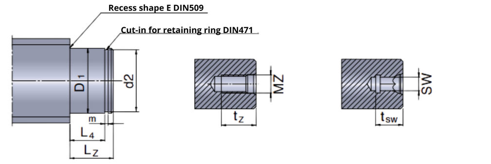
Dimension table for loose bearing journals
| Loose bearing journals: B | Machining options: K- hexagonal socket, G- – internal thread | |||||||||||
|---|---|---|---|---|---|---|---|---|---|---|---|
| Size | Dimensions [mm] | Center hole incl. internal thread | Hexagonal socket | ||||||||
| d0 | P | D1h6 | Lz | L4 | d2 | d2 tolerance | m H13 | MZ | tz | SW | tsw |
| 16 | 5/10 | 10 | 12 | 9 | 9.6 | h10 | 1.10 | 4 | 5 | ||
| 20 | 5/10/20 | 12 | 13 | 10 | 11.5 | h11 | 1.10 | M4 | 10 | 4 | 5 |
| 25 | 5/10/20/25 | 17 | 15 | 12 | 16.2 | h11 | 1.10 | M6 | 16 | 5 | 5 |
| 32 | 5/10/20/32 | 20 | 18 | 14 | 19.0 | h11 | 1.30 | M6 | 16 | 5 | 5 |
| 40 | 5/10/20/40 | 30 | 20 | 16 | 28.6 | h12 | 1.60 | M10 | 22 | 10 | 10 |
| 50 | 10/20 | 35 | 22 | 17 | 33.0 | h12 | 1.60 | M12 | 28 | 12 | 12 |
| 63 | 10/20 | 50 | 27 | 20 | 47.0 | h12 | 2.15 | M16 | 36 | 17 | 12 |
| 80 | 10 | 60 | 29 | 22 | 57.0 | h12 | 2.15 | M20 | 42 | 17 | 12 |
Ball Return Systems
Steinmeyer, like other global manufacturers, applies all commonly used ball return systems. For rolled ball screw assemblies, the standard solution is a multi-liner ball return. External ball return systems are also applied by Steinmeyer either in the form of a through-the-nut or an end-cap return.
Multiliner (internal return)


Multiliners lift the balls out of the track and guide them over the outer diameter of the shaft into the next available track. This type of internal return is particularly compact and yields the smallest nut diameters of any ball return system. It is also the ball return of choice for very small ball sizes and small leads
Through-the-nut return (external return)


Steinmeyer‘s UltraSpeed return is normally used for lead/diameter ratios greater than 0.5. It is normally used with dual start threads. Balls are lifted off the shaft using a deflector at one end of the nut and then guided through a bore (internal to the nut body) to the other end of the nut, where a similar piece guides the balls back onto the thread. One pair of deflectors serves one circuit (i.e. one of the threads), which includes several turns.
End-cap return (external return)


End cap return works very much like the previously described throughthe-nut return, with the exception that the ball deflector function is executed using a cap that is integrated onto the front of the nut along with the wiper. End cap return is normally used for very large lead/diameter ratios


