
Linear guides
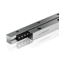
Linear guides form the basis of a linear bearing. They usually take the form of a metal strip with fixing holes and a raceway for the rolling elements of the bearing cages. The raceway can be flat or profiled. The main task of linear guides is to transfer pressure from the machine parts to which they are bolted to the rolling elements and to provide the rolling elements with the best possible conditions for correct operation.


RD
General Information
The RD-type linear guides, featuring a double V-profile, complement the R-type linear guides and enable compact design solutions.
The same as R-type guideways, RD guideways are compatible with ball bearing cages (types AK or RKK) and cross-roller bearing cages (types AA, AC, or RRK).
By default, RD-type linear guides are manufactured from tool steel grade 1.2842, with a hardness range of 58-62 HRC. RD1 and RD2 variants are made from tool steel grade 1.3505.
The stainless steel version is made from tool steel grade 1.4034 and features a hardness between 58-64HRC.
Technical drawing of RD type linear guides, combined with the R-type linear guides

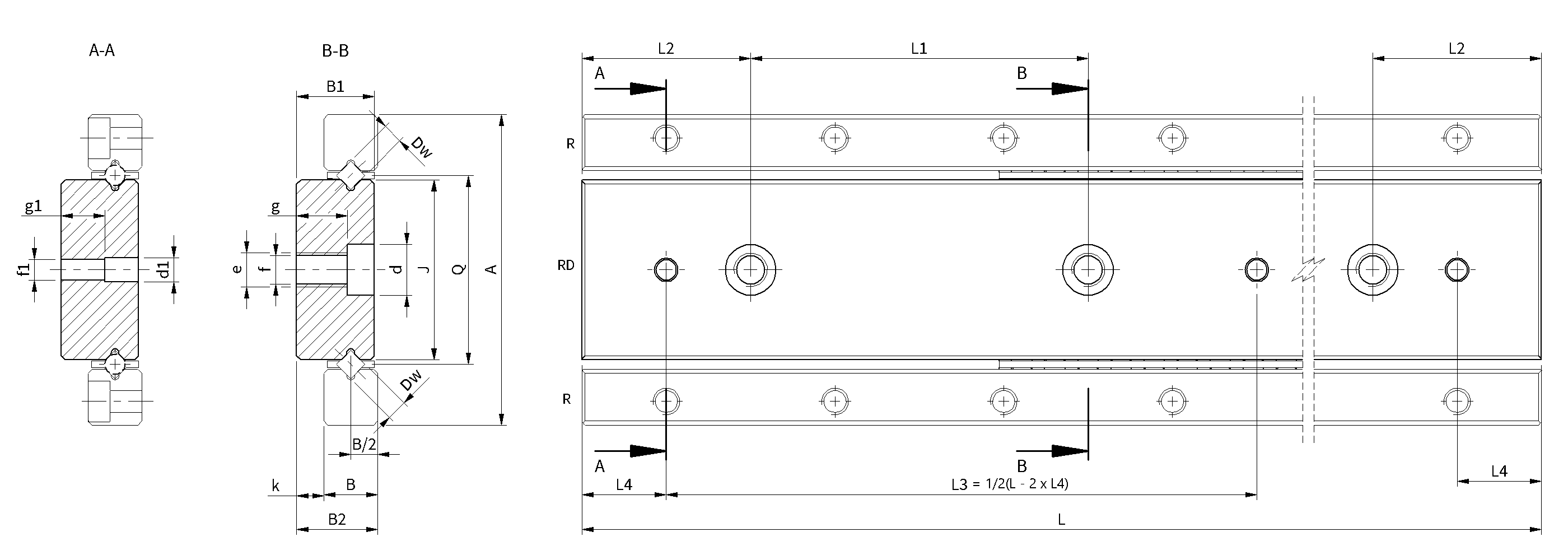
Dimension table of RD type linear guides, combined with the R-type linear guides
|
Type
|
Dimensions
|
Fixing holes
|
|||||||||||||
|---|---|---|---|---|---|---|---|---|---|---|---|---|---|---|---|
|
A*
|
B
|
B1
|
B2
|
DW
|
J
|
Q
|
k
|
d
|
d1
|
e
|
f
|
f1
|
g
|
g1
|
|
|
RD1
|
22
|
4
|
5.5
|
6
|
1.5
|
12.8
|
13.5
|
2
|
4.4
|
-
|
M3
|
2.55
|
3 H7
|
3.5
|
-
|
|
RD2
|
30
|
6
|
8.5
|
9
|
2
|
17
|
18
|
3
|
6
|
-
|
M4
|
3.35
|
3 H7
|
5.4
|
-
|
|
RD3
|
46
|
8
|
11.5
|
12
|
3
|
26.6
|
28
|
4
|
7.5
|
3.5
|
M5
|
4.2
|
3 H7
|
7.3
|
6.5
|
|
RD6
|
76
|
15
|
19
|
20
|
6
|
41.8
|
45
|
5
|
9.5
|
6.5
|
M6
|
5.2
|
6 H7
|
13.8
|
12
|
|
RD9
|
116
|
22
|
27
|
28
|
9
|
67.4
|
72
|
6
|
10.5
|
8.5
|
M8
|
6.8
|
8 H7
|
20.8
|
16
|
|
RD12
|
135
|
28
|
34
|
35
|
12
|
70.8
|
77
|
7
|
13.5
|
10.5
|
M10
|
8.5
|
10 H7
|
25.8
|
20
|
|
* together with the R-type linear guides |
|||||||||||||||
Table of available lengths and accessories
|
Type
|
L
[mm] |
L1
|
L2
|
L4
|
Bearing cage
|
|---|---|---|---|---|---|
| RD1 | 100 150 200 | 25 | 12,5 | 5 | AA1 RRK1 RKK1 |
| RD2 | 200 300 400 | 50 | 25 | 12,5 | AA2 RRK2 RKK2 |
| RD3 | 300 400 500 600 800 | 50 | 25 | 12,5 | AA3 RRK3 RKK3 |
| RD6 | na zapytanie | 100 | 50 | 25 | AA6 RRK6 RKK6 |
| RD9 | na zapytanie | 100 | 50 | 25 | AA9 RRK9 RKK9 |
| RD12 | na zapytanie | 100 | 50 | 25 | AA12 RRK12 RKK12 |


