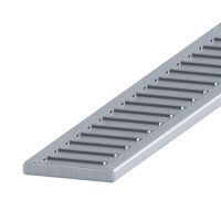
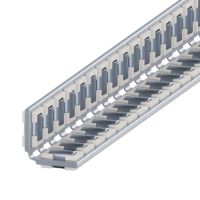
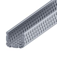
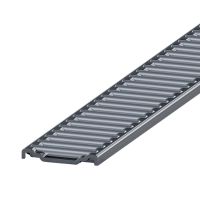
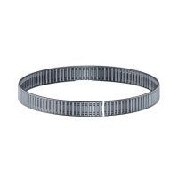
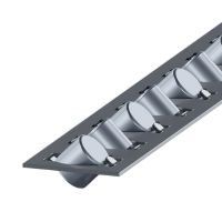
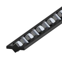
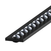
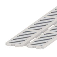
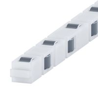
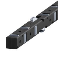
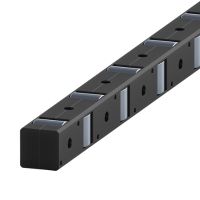
The linear bearing cage is an essential component of a linear rolling bearing built with the use of linear guides. The main task of the bearing cage is to hold the rolling elements inside the bearing on the guide's raceways in the correct operating position.
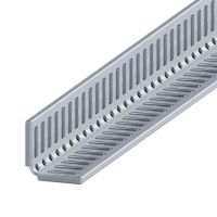
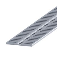
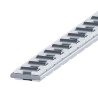
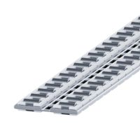
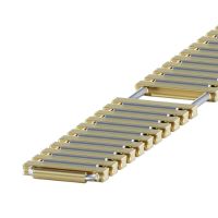
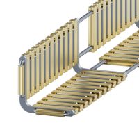
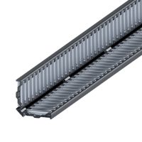
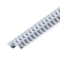
Angular double-row plastic bearing cages with bearing needles
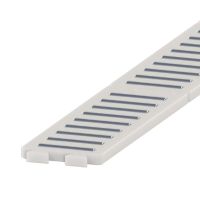
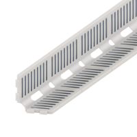
Made of abrasion resistant plastic.
Working temperature up to do 120°C.
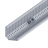
Cage sides are symmetrically bent at the right angle towards each other.
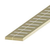
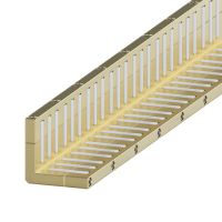
Applicable areas include also linear guides of the types "M" and "V", "RM", "RV", "N" and "O"
Technical drawing of FFW bearing cages
Dimension table of FFW bearing cages
Needle
diameter
Ø
Type
/symbol
Dimensions
Load capacity *
A
DW
LW
a
LK
max
Ze
C
[N]
CO
[N]
2
FFW 2025
15
2
6.8
2
32
7
25 900
87 500
2.5
FFW 2535
20.5
2.5
9.8
2.4
45
8
39 600
130 500
3
FFW 3045
26
3
13.8
3
60
9
57 900
188 400
3.5
FFW 3555
31.5
3.5
17.8
3.2
75
10
78 400
250 800
*) - Load capacity for the theoretical length of the cage of 100 mm with the thrust force "F" in accordance to the drawing.
- The load capacity is calculated for guides with hardness of 60 +/- 2 HRc oand surface roughness of Ra<0.4.
- Load capacity of bearing cages is calculated on the basis of number of bearing needles mounted in the cage.
- Cage i composwed of parts. Le - length of 1 part. Ze - number of neadels in 1 row of 1 part.
Weight table of FFW bearing cages
Table for weight values of bearing cages
(for the length of Lk=1000 mm) [g]
Type/symbol
Plastic
FFW 2025
94
FFW 2535
182
FFW 3045
315
FFW 3555
464
Precision
Sorting tolerance
up to 0.5 µm
Quality
Quality Management System
compliant with ISO 9001:2015
Experience
Over 20 years of expertise
in linear technology.
Customization
We manufacture components
tailored to individual requirements